8 パス
目次
8.1 概要
パスはフィルやストロークが可能な図形の外形線を表現する。(
フィル, ストローク, ペイントサーバ
を見よ。)
Paths represent the outline of a shape which can be filled or stroked. (See Filling, Stroking and Paint Servers.)
パスは「現在の点」という概念を用いて説明される。紙にペンで描くことに例えるなら、現在の点とはペンが指す地点になる。ペンの位置は変化することができ、(開いているか閉じている)図形の外形線を直線でも曲線でもペンを動かして辿ることができる。
A path is described using the concept of a current point. In an analogy with drawing on paper, the current point can be thought of as the location of the pen. The position of the pen can be changed, and the outline of a shape (open or closed) can be traced by dragging the pen in either straight lines or curves.
パスはオブジェクトの幾何学的外形線を表現し、moveto(現在の点を新しく設定する), lineto(直線を描く), curveto(三次ベジェ曲線を描く), closepath(線を直近の moveto まで描いて現在の図形を閉じる)などの語で定義される。オブジェクトに「ドーナツの穴」を作るような複合パス(複数の部分パスを含むパス)も可能である。
Paths represent the geometry of the outline of an object, defined in terms of moveto (set a new current point), lineto (draw a straight line), curveto (draw a curve using a cubic Bézier) and closepath (close the current shape by drawing a line to the last moveto) elements. Compound paths (i.e., a path with multiple subpaths) are possible to allow effects such as "donut holes" in objects.
この章では SVG パスの構文とふるまいについて述べる。 SVG のパスの実装における様々な注意点は
path 要素の実装における注意
で述べる。
This chapter describes the syntax and behavior for SVG paths. Various implementation notes for SVG paths can be found in 'path' element implementation notes.
SVG のパスは
'path'
要素を用いて定義される。
A path is defined in SVG using the 'path' element.
8.2 'path' 要素
属性定義:
- d = "<path-data>"
図形の外形線の定義。
パスデータ
を見よ。属性値を空(d="")にすると要素は描画されなくなる。
省略値
は空の文字列。
The definition of the outline of a shape. See Path data. An empty attribute value (d="") disables rendering of the element. The lacuna value is the empty string.
アニメーション:可
, ただし、
パスデータのアニメーション
で述べる制限を見よ。
Animatable: yes, but see restrictions described in Animating path data.
- pathLength = "<number>"
利用単位
で表される、文書作成者により定められるパスの長さ。この値は UA における
パスに沿う距離
の計算を調整するために用いられる。 UA は自身が計算したパスの全長の
pathLength
に対する比率ですべてのパスに沿う距離の計算を等倍するものとする。
pathLength
は
モーション・アニメーション
および、種々の
ストローク処理
の計算に作用し得る。
The authoring length of the path, in user units. This value is used to calibrate the user agent's own distance-along-a-path calculations with that of the author. The user agent shall scale all distance-along-a-path computations by the ratio of 'pathLength' to the user agent's own computed value for total path length. 'pathLength' potentially affects calculations for motion animation and various stroke operations.
負値は
サポート外の値
。
A negative value is an unsupported value.
アニメーション:可
- focusable = "true" | "false" | "auto"
詳細は
属性定義
を見よ。
See attribute definition for description.
アニメーション:可
- ナビゲーション属性
定義
を見よ。
See definition.
8.2.1 パスデータのアニメーション
補間パスデータ・アニメーションは、アニメーションの指定におけるそれぞれの
正規化
されたパスデータの指定が
d
属性の
正規化
された後のパスデータ命令と全く同じリストになるときにのみ可能になる。これはそれぞれのパスデータの指定と
d
属性が
パスの正規化
に定められる正規化に則った正規化後に全く同じ命令のリストになることを意味する。アニメーションが指定されたときにパスデータの命令が同じにならない場合、アニメーションの指定は
サポート外
として無視されなければならない。
アニメーションエンジンは各パスデータ命令の各パラメタを与えられた
アニメーション要素
の属性に基づいて個別に補間するものとする。
Interpolated path data animation is only possible when each normalized path data specification within an animation specification has exactly the same list of path data commands as the 'd' attribute after normalization. This means that each path data specification and the 'd' attribute would have the exact same list of commands if normalized as defined in Path Normalization. If an animation is specified and the list of path data commands is not the same, then the animation specification must be ignored as unsupported. The animation engine shall interpolate each parameter to each path data command separately based upon the attributes on the given animation element.
非補間パスデータ・アニメーション(すなわち calcMode="discrete" )は常に可能である。
Non-interpolated (i.e. calcMode="discrete") path data animation is always possible.
8.3 パスデータ
パスは moveto, lineto, curveto(三次および二次のベジェ曲線), closepath 命令で記述される
d
属性を持つ
path
要素で定義される。
A path is defined by including a 'path' element which contains a 'd' attribute, where the 'd' attribute contains the moveto, line, curve (both cubic and quadratic Béziers) and closepath instructions.
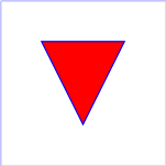
Example 08_01 は三角形の
path
を指定している( M は moveto, L は lineto, z は closepath を意味する)。
Example 08_01 specifies a 'path' in the shape of a triangle. (The M indicates a moveto, the L's indicate lineto's, and the z indicates a closepath).
<?xml version="1.0"?>
<svg width="4cm" height="4cm" viewBox="0 0 400 400"
     xmlns="http://www.w3.org/2000/svg" version="1.2" baseProfile="tiny">
  <!-- 'path' の単純な例 -->
  <title>Example triangle01- simple example of a 'path' </title>
  <!-- 三角形を描くパス -->
  <desc> A path that draws a triangle </desc>
  <rect x="1" y="1" width="398" height="398"
        fill="none" stroke="blue" />
  <path d="M 100 100 L 300 100 L 200 300 z"
        fill="red" stroke="blue" stroke-width="3" />
</svg>
パスデータは読み易くするために改行を入れて複数行に渡らせてもよい。
Path data can contain newline characters and thus can be broken up into multiple lines to improve readability.
多くの場合、 SVG ファイルの大半はパスデータで占められるので、ファイルサイズを減量してダウンロードの効率を高められるようにするため、パスデータの構文は簡潔なものになっている。 SVG においてはパスデータ量を減らすため、次に挙げる工夫が施されている:
The syntax of path data is concise in order to allow for minimal file size and efficient downloads, since many SVG files will be dominated by their path data. Some of the ways that SVG attempts to minimize the size of path data are as follows:
すべての命令は一個の文字で表記される(例えば moveto は M で表記される)。
All instructions are expressed as one character (e.g., a moveto is expressed as an M).
余分な空白やコンマなどの区切り文字は省ける(例えば 'M 100 100 L 200 200' には不要な空白も含まれているので、よりコンパクトに 'M100 100L200 200' と表記できる)
Superfluous white space and separators such as commas can be eliminated (e.g., 'M 100 100 L 200 200' contains unnecessary spaces and could be expressed more compactly as 'M100 100L200 200').
同じ命令が続く場合、後続の命令では命令文字を省ける(例えば 'M 100 200 L 200 100 L -100 -200' の2番目の "L" を取り除いて 'M 100 200 L 200 100 -100 -200' と記述してもよい)。
The command letter can be eliminated on subsequent commands if the same command is used multiple times in a row (e.g., you can drop the second "L" in 'M 100 200 L 200 100 L -100 -200' and use 'M 100 200 L 200 100 -100 -200' instead).
すべての命令に対し、その相対版がある(大文字は絶対座標、小文字は相対座標を意味する)。
Relative versions of all commands are available (uppercase means absolute coordinates, lowercase means relative coordinates).
水平線と垂直線の記述を簡略化するために lineto の別形式が用意されている(絶対/相対の両方に)。
Alternate forms of lineto are available to optimize the special cases of horizontal and vertical lines (absolute and relative).
現在のパス区分の一部の制御点が前のパス区分の制御点から自動的に定まる場合に記述を簡略化する curveto の別形式が用意されている。
Alternate forms of curve are available to optimize the special cases where some of the control points on the current segment can be determined automatically from the control points on the previous segment.
パスデータの構文は接頭辞表記法である(すなわちパラメタが命令文字の後に続く)。小数点は Unicode U+002E FULL STOP(".")文字( Unicode においては PERIOD または dot または decimal point とも称される)
[UNICODE]
のみが許され、他の区切り文字は許されない(例えばパスデータの中では数値 "13,000.56" は無効であり、代わりに "13000.56" 等と表記する)。
The path data syntax is a prefix notation (i.e., commands followed by parameters). The only allowable decimal point is a Unicode U+002E FULL STOP (".") character (also referred to in Unicode as PERIOD, dot and decimal point) [UNICODE] and no other delimiter characters are allowed. (For example, the following is an invalid numeric value in path data: "13,000.56". Instead, say: "13000.56".)
相対版の命令における座標はすべて命令開始時の現在の点から相対的なものとする。
For the relative versions of the commands, all coordinate values shall be relative to the current point at the start of the command.
以下の表の中では、次の表記が用いられる:
In the tables below, the following notation is used:
-
(): パラメタのグループ化
(): grouping of parameters
-
+: 1つ以上のパラメタが要求される
+: 1 or more of the given parameter(s) is required
-
大文字の命令(例えば M)に後続する座標成分は絶対座標として扱うものとする。
Coordinates following commands in uppercase (e.g., M) shall be treated as absolute coordinates.
-
小文字の命令(例えば m)に後続する座標成分は相対座標として扱うものとする。
Coordinates following commands in lowercase (e.g., m) shall be treated as relative coordinates.
以下の節で命令を列挙する。
The following sections list the commands.
8.3.2 "moveto" 命令
'moveto'
命令(M または m)は、現在の点を新たに設定する。ペンを持ち上げて新たな地点へ動かしたかのような効果になる。パスデータは
'moveto'
命令から開始されなければならない。後続の
'moveto'
命令(すなわち最初の命令でない
'moveto'
)は新しい部分パスの開始を意味する:
The 'moveto' commands (M or m) establish a new current point. The effect is as if the "pen" were lifted and moved to a new location. A path data segment (if there is one) must begin with a 'moveto' command. Subsequent 'moveto' commands (i.e., when the 'moveto' is not the first command) represent the start of a new subpath:
| 命令 |
名称 |
パラメタ |
説明 |
M (絶対)
m (相対) |
moveto |
(x y)+ |
座標 (x,y) から新たな部分パスを開始させるものとする。これにより現在の点も新たに与えられた座標に設定されるものとする。相対の
'moveto'
(m) が
path
の最初に現れた場合、パラメタは絶対座標として扱うものとする。
'moveto'
の後に余分な座標(座標成分のペア)が与えられた場合、それらの座標は暗黙に
'lineto'
命令のパラメタとして扱うものとする。
【
SVG 1.1 の正誤表
より:相対の 'moveto' (m) が現れた場合の暗黙の 'lineto' の座標は(最初の moveto であっても)相対座標として扱うものとする。】
A new sub-path at the given (x,y) coordinate shall be started. This shall also establish a new current point at the given coordinate. If a relative 'moveto' ( m ) appears as the first element of the 'path' , then it shall treated as a pair of absolute coordinates. If a 'moveto' is followed by multiple pairs of coordinates, the subsequent pairs shall be treated as implicit 'lineto' commands.
|
8.3.3 "closepath" 命令
現在の点から現在の部分パスの始点へ直線を描き、現在の部分パスを終了させるものとする。もし
'closepath'
(Z または z)の直後に他の命令が続く場合、次の部分パスは現在の部分パスの始点と同じ点から開始されなければならない。
A straight line shall be drawn from the current point to the initial point of the current subpath, and shall end the current subpath. If a 'closepath' (Z or z) is followed immediately by any other command, then the next subpath must start at the same initial point as the current subpath.
'closepath'
により部分パスが終了した場合と、
'lineto'
命令により部分パスを「手動で」閉じた場合の
stroke-linejoin
と
stroke-linecap
に対するふるまいは異なる。
'closepath'
により部分パスが閉じられた場合、部分パスの最後の区分と最初の区分の端点は現在の
stroke-linejoin
の値を用いて「連結」されるものとする。一方、
'lineto'
命令により「手動で」部分パスが閉じられた場合、現在の部分パスの最後の区分と最初の区分の端点は連結されず、それぞれ現在の
stroke-linecap
の値を用いて端点が形状付けられるものとする。
'closepath'
命令終了時の現在の点は現在の部分パスの始点に更新されるものとする。
When a subpath ends in a 'closepath', it differs in behavior from what happens when "manually" closing a subpath via a 'lineto' command in how 'stroke-linejoin' and 'stroke-linecap' are implemented. With 'closepath', the end of the final segment of the subpath shall be "joined" with the start of the initial segment of the subpath using the current value of 'stroke-linejoin'. If instead the subpath is closed "manually" via a 'lineto' command, the start of the first segment and the end of the last segment are not joined but instead shall each be capped using the current value of 'stroke-linecap'. At the end of the command, the new current point shall be set to the initial point of the current subpath.
| 命令 |
名称 |
パラメタ |
説明 |
Z
または
z |
closepath |
(なし) |
現在の点から現在の部分パスの始点まで直線を描いて現在の部分パスを閉じ、その始点を新たに現在の点にするものとする。 Z と z はパラメタをとらないので効果は同じである。
The current subpath shall be closed by drawing a straight line from the current point to current subpath's initial point, which then shall become the new current point. Since the Z and z commands take no parameters, they have an identical effect.
|
8.3.4 "lineto" 命令
現在の点から新しい点へ直線を描かせる種々の
'lineto'
命令がある:
The various 'lineto' commands draw straight lines from the current point to a new point:
| 命令 |
名称 |
パラメタ |
説明 |
L (絶対)
l (相対) |
lineto |
(x y)+ |
現在の点から座標 (x,y) へ直線を描き、現在の点をその座標に更新するものとする。パラメタに複数個の座標が与えられた場合、折れ線( polyline )が描かれるものとする。命令終了時の現在の点は最後の座標に更新されるものとする。
A line shall be drawn from the current point to the given (x,y) coordinate, which then shall become the new current point. If more than one coordinate pair is specified, a polyline shall be drawn. At the end of the command, the new current point shall be set to the final set of coordinates provided.
|
H (絶対)
h (相対) |
horizontal lineto |
x+ |
現在の点 (cpx, cpy) から (x, cpy) へ水平線を描くものとする。 x を複数個与えた場合、水平線も複数本描かれるものとする(通常は意味をなさないが)。命令終了時の現在の点は最後の x に対応する座標 (x, cpy) に更新されるものとする。
A horizontal line shall be drawn from the current point (cpx, cpy) to (x, cpy). If more than one x value is specified, multiple horizonal lines shall be drawn (although usually this doesn't make sense). At the end of the command, the new current point shall be (x, cpy) for the final value of x.
|
V (絶対)
v (相対) |
vertical lineto |
y+ |
現在の点 (cpx, cpy) から (cpx, y) へ垂直線を描くものとする。 y を複数個与えた場合、垂直線も複数本描かれるものとする(通常は意味をなさないが)。命令終了時の現在の点は最後の y に対応する座標 (cpx, y) に更新されるものとする。
A vertical line shall be drawn from the current point (cpx, cpy) to (cpx, y). If more than one y value is specified, multiple vertical lines shall be drawn (although usually this doesn't make sense). At the end of the command, the new current point shall be (cpx, y) for the final value of y.
|
8.3.5 曲線命令
これらの命令群は曲線を描く:
These groups of commands draw curves:
-
三次ベジェ命令
(C, c, S and s)。
三次ベジェパス区分は始点および終点と二つの制御点で定義される。
Cubic Bézier commands (C, c, S and s). A cubic Bézier segment is defined by a start point, an end point, and two control points.
-
二次ベジェ命令
(Q, q, T, t)。
二次ベジェパス区分は始点および終点と一つの制御点で定義される。
Quadratic Bézier commands (Q, q, T and t). A quadratic Bézier segment is defined by a start point, an end point, and one control point.
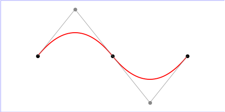
8.3.6 三次ベジェ曲線命令
'三次ベジェ'命令は次のようになる:
The 'Cubic Bézier' commands are as follows:
| 命令 |
名称 |
パラメタ |
説明 |
C (絶対)
c (相対) |
curveto |
(x1 y1 x2 y2 x y)+ |
現在の点から、点 (x, y) へ、 (x1, y1) を曲線の始点に対する制御点(第一制御点)、 (x2, y2) を曲線の終点に対する制御点(第二制御点)として、三次ベジェ曲線を描くものとする。複数個の座標が与えられた場合、複ベジェ曲線を描くものとする。命令終了時の現在の点は複ベジェに用いられた最後の座標 (x, y) に更新されるものとする。
A cubic Bézier curve shall be drawn from the current point to (x,y) using (x1,y1) as the control point at the beginning of the curve and (x2,y2) as the control point at the end of the curve. If multiple sets of coordinates are specified, a polybézier shall be drawn. At the end of the command, the new current point shall be the final (x,y) coordinate pair used in the polybézier.
|
S (絶対)
s (相対) |
shorthand / smooth curveto |
(x2 y2 x y)+ |
現在の点から点 (x, y) へ三次ベジェ曲線を描くものとする。第一制御点は直前の命令の第二制御点に対し現在の点を中心とする点対称の地点になるものとする(もし直前の命令が存在しない、あるいは C, c, S, s のいずれでもない場合、第一制御点は現在の点と同一のものとする)。 (x2, y2) は第二制御点になるものとする(曲線の終点に対する制御点)。複数個の座標が与えられた場合、複ベジェ曲線を描くものとする。命令終了時の現在の点は複ベジェに用いられた最後の座標 (x, y) に更新されるものとする。
A cubic Bézier curve shall be drawn from the current point to (x,y). The first control point shall be the reflection of the second control point on the previous command relative to the current point. (If there is no previous command or if the previous command was not an C, c, S or s, the first control point shall be coincident with the current point.) (x2,y2) shall be used as the second control point (i.e., the control point at the end of the curve). If multiple sets of coordinates are specified, a polybézier shall be drawn. At the end of the command, the new current point shall be the final (x,y) coordinate pair used in the polybézier.
|
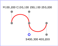
Example 08_02 に
path
における
'三次ベジェ'
命令の単純な利用を示す。"S" 命令の制御点が前の "C" 命令の制御点から "S" 命令の始点を中心に点対称になる点として自動的に算出されることに注意。
Example 08_02 shows some simple uses of 'Cubic Bézier' commands within a 'path'. Note that the control point for the "S" command is computed automatically as the reflection of the control point for the previous "C" command relative to the start point of the "S" command.
<?xml version="1.0"?>
<svg width="5cm" height="4cm" viewBox="0 0 500 400"
     xmlns="http://www.w3.org/2000/svg" version="1.2" baseProfile="tiny">
  <!-- パスデータの中の三次ベジェ命令 -->
  <title>Example cubic01- cubic Bézier commands in path data </title>
  <!-- "C" と "S" 命令を用いたパスデータの単純な例を
        制御点と端点を示して図解 -->
  <desc> Picture showing a simple example of path data
        using both a "C" and an "S" command,
        along with annotations showing the control points
        and end points </desc>
  <rect fill="none" stroke="blue" stroke-width="1" x="1" y="1" width="498" height="398" />
  <polyline fill="none" stroke="#888888" stroke-width="1" points="100,200 100,100" />
  <polyline fill="none" stroke="#888888" stroke-width="1" points="250,100 250,200" />
  <polyline fill="none" stroke="#888888" stroke-width="1" points="250,200 250,300" />
  <polyline fill="none" stroke="#888888" stroke-width="1" points="400,300 400,200" />
  <path fill="none" stroke="red" stroke-width="5" d="M100,200 C100,100 250,100 250,200
                                       S400,300 400,200" />
  <circle fill="#888888" stroke="none" stroke-width="2" cx="100" cy="200" r="10" />
  <circle fill="#888888" stroke="none" stroke-width="2" cx="250" cy="200" r="10" />
  <circle fill="#888888" stroke="none" stroke-width="2" cx="400" cy="200" r="10" />
  <circle fill="#888888" stroke="none" cx="100" cy="100" r="10" />
  <circle fill="#888888" stroke="none" cx="250" cy="100" r="10" />
  <circle fill="#888888" stroke="none" cx="400" cy="300" r="10" />
  <circle fill="none" stroke="blue" stroke-width="4" cx="250" cy="300" r="9" />
  <text font-size="22" font-family="Verdana" x="25" y="70">M100,200 C100,100 250,100 250,200</text>
  <text font-size="22" font-family="Verdana" x="325" y="350"
        text-anchor="middle">S400,300 400,200</text>
</svg>
次の画像に制御点により三次ベジェ曲線がどのように変化するかを示す。最初の5例は単一の三次ベジェパス区分である。右側一番下の例は "C" 命令に続く "S" 命令を示している。
The following picture shows some how cubic Bézier curves change their shape depending on the position of the control points. The first five examples illustrate a single cubic Bézier path segment. The example at the lower right shows a "C" command followed by an "S" command.
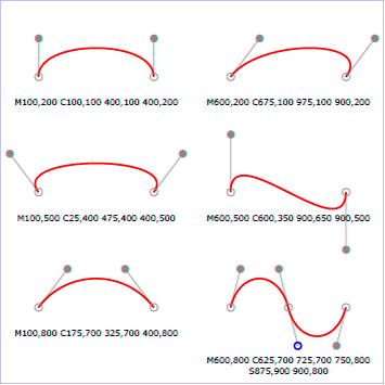
この例を SVG として表示( SVG 対応ブラウザのみ)
8.3.7 二次ベジェ 曲線命令
'二次ベジェ'命令は次のようになる:
The 'Quadratic Bézier' commands are as follows:
| 命令 |
名称 |
パラメタ |
説明 |
Q (絶対)
q (相対) |
二次ベジェ curveto |
(x1 y1 x y)+ |
現在の点から制御点 (x1, y1) を用いて点 (x, y) へ二次ベジェ曲線を描く。複数個の座標が与えられた場合、複ベジェ曲線を描くものとする。命令終了時の現在の点は複ベジェに用いられた最後の座標 (x, y) に更新されるものとする。
A quadratic Bézier curve is drawn from the current point to (x,y) using (x1,y1) as the control point. If multiple sets of coordinates are specified, a polybézier shall be drawn. At the end of the command, the new current point shall be the final (x,y) coordinate pair used in the polybézier.
|
T (絶対)
t (相対) |
shorthand / smooth quadratic Bézier curveto |
(x y)+ |
現在の点から点 (x, y) へ二次ベジェ曲線を描く。制御点は直前の命令の制御点に対し現在の点を中心とする点対称の地点になるものとする(もし直前の命令が存在しない、あるいは Q, q, T, t のいずれでもない場合、制御点は現在の点と同一のものとする)。複数個の座標が与えられた場合、複ベジェ曲線を描くものとする。命令終了時の現在の点は複ベジェに用いられた最後の座標 (x, y) に更新されるものとする。
A quadratic Bézier curve is drawn from the current point to (x,y). The control point shall be the reflection of the control point on the previous command relative to the current point. (If there is no previous command or if the previous command was not a Q, q, T or t, the control point shall be current point.) If multiple sets of coordinates are specified, a polybézier shall be drawn. At the end of the command, the new current point shall be the final (x,y) coordinate pair used in the polybézier.
|
Example quad01
にパスにおける
'二次ベジェ'
命令の単純な利用を示す。"T" 命令の制御点が前の "Q" 命令の制御点から "T" 命令の始点を中心に点対称になる点として自動的に計算されることに注意。
Example quad01 shows some simple uses of 'Quadratic Bézier' commands within a path. Note that the control point for the "T" command is computed automatically as the reflection of the control point for the previous "Q" command relative to the start point of the "T" command.
<?xml version="1.0"?>
<!DOCTYPE svg PUBLIC "-//W3C//DTD SVG 1.1//EN"
  "http://www.w3.org/Graphics/SVG/1.1/DTD/svg11.dtd">
<svg width="12cm" height="6cm" viewBox="0 0 1200 600"
     xmlns="http://www.w3.org/2000/svg" version="1.2" baseProfile="tiny">
  <!-- パスデータにおける二次ベジェ命令 -->
  <title>Example quad01 - quadratic Bezier commands in path data </title>
  <!-- "Q" と "T" 命令を制御点と端点を示して図解 -->
  <desc> Picture showing a "Q" a "T" command,
         along with annotations showing the control points
         and end points </desc>
  <rect x="1" y="1" width="1198" height="598"
        fill="none" stroke="blue" stroke-width="1" />
  <path d="M200,300 Q400,50 600,300 T1000,300"
        fill="none" stroke="red" stroke-width="5"  />
  <!-- 端点 -->
  <!-- End points -->
  <g fill="black" >
    <circle cx="200" cy="300" r="10"/>
    <circle cx="600" cy="300" r="10"/>
    <circle cx="1000" cy="300" r="10"/>
  </g>
  <!-- 制御点、および端点から制御点への線 -->
  <!-- Control points and lines from end points to control points -->
  <g fill="#888888" >
    <circle cx="400" cy="50" r="10"/>
    <circle cx="800" cy="550" r="10"/>
  </g>
  <path d="M200,300 L400,50 L600,300
           L800,550 L1000,300"
        fill="none" stroke="#888888" stroke-width="2" />
</svg>
8.3.8 パスデータの構文
以下に Extended Backus-Naur 形式 [EBNF] によるパスデータの構文を示す:
The following description of the grammar for path data uses Extended Backus-Naur Form [EBNF]:
path-data ::=
    wsp* moveto-drawto-command-groups? wsp*
moveto-drawto-command-groups ::=
    moveto-drawto-command-group
    | moveto-drawto-command-group wsp* moveto-drawto-command-groups
moveto-drawto-command-group ::=
    moveto wsp* drawto-commands?
drawto-commands ::=
    drawto-command
    | drawto-command wsp* drawto-commands
drawto-command ::=
    closepath
    | lineto
    | horizontal-lineto
    | vertical-lineto
    | curveto
    | smooth-curveto
    | quadratic-bezier-curveto
    | smooth-quadratic-bezier-curveto
moveto ::=
    ( "M" | "m" ) wsp* moveto-argument-sequence
moveto-argument-sequence ::=
    coordinate-pair
    | coordinate-pair comma-wsp? lineto-argument-sequence
closepath ::=
    ("Z" | "z")
lineto ::=
    ( "L" | "l" ) wsp* lineto-argument-sequence
lineto-argument-sequence ::=
    coordinate-pair
    | coordinate-pair comma-wsp? lineto-argument-sequence
horizontal-lineto ::=
    ( "H" | "h" ) wsp* horizontal-lineto-argument-sequence
horizontal-lineto-argument-sequence ::=
    coordinate
    | coordinate comma-wsp? horizontal-lineto-argument-sequence
vertical-lineto ::=
    ( "V" | "v" ) wsp* vertical-lineto-argument-sequence
vertical-lineto-argument-sequence ::=
    coordinate
    | coordinate comma-wsp? vertical-lineto-argument-sequence
curveto ::=
    ( "C" | "c" ) wsp* curveto-argument-sequence
curveto-argument-sequence ::=
    curveto-argument
    | curveto-argument comma-wsp? curveto-argument-sequence
curveto-argument ::=
    coordinate-pair comma-wsp? coordinate-pair comma-wsp? coordinate-pair
smooth-curveto ::=
    ( "S" | "s" ) wsp* smooth-curveto-argument-sequence
smooth-curveto-argument-sequence ::=
    smooth-curveto-argument
    | smooth-curveto-argument comma-wsp? smooth-curveto-argument-sequence
smooth-curveto-argument ::=
    coordinate-pair comma-wsp? coordinate-pair
quadratic-bezier-curveto ::=
    ( "Q" | "q" ) wsp* quadratic-bezier-curveto-argument-sequence
quadratic-bezier-curveto-argument-sequence ::=
    quadratic-bezier-curveto-argument
    | quadratic-bezier-curveto-argument comma-wsp?
        quadratic-bezier-curveto-argument-sequence
quadratic-bezier-curveto-argument ::=
    coordinate-pair comma-wsp? coordinate-pair
smooth-quadratic-bezier-curveto ::=
    ( "T" | "t" ) wsp* smooth-quadratic-bezier-curveto-argument-sequence
smooth-quadratic-bezier-curveto-argument-sequence ::=
    coordinate-pair
    | coordinate-pair comma-wsp? smooth-quadratic-bezier-curveto-argument-sequence
coordinate-pair ::=
    coordinate comma-wsp? coordinate
coordinate ::=
    number
nonnegative-number ::=
    integer-constant
    | floating-point-constant
number ::=
    sign? integer-constant
    | sign? floating-point-constant
flag ::=
    "0" | "1"
comma-wsp ::=
    (wsp+ comma? wsp*) | (comma wsp*)
comma ::=
    ","
integer-constant ::=
    digit-sequence
floating-point-constant ::=
    fractional-constant exponent?
    | digit-sequence exponent
fractional-constant ::=
    digit-sequence? "." digit-sequence
    | digit-sequence "."
exponent ::=
    ( "e" | "E" ) sign? digit-sequence
sign ::=
    "+" | "-"
digit-sequence ::=
    digit
    | digit digit-sequence
digit ::=
    "0" | "1" | "2" | "3" | "4" | "5" | "6" | "7" | "8" | "9"
wsp ::=
    (#x20 | #x9 | #xD | #xA)
EBNF の処理におけるトークンの生成では、条件を満たさない文字に出会うまで可能な限り多くの文字が消費されなければならない。従って、文字列 'M 100-200' では "moveto" の最初の座標成分に対し文字列 "100" が消費され、マイナス記号の手前で止まる(座標の生成ではマイナス記号が数字の後に続くことはないので)。その結果、最初の座標成分は "100" になり、次の座標成分は "-200" になる。
The processing of the EBNF must consume as much of a given EBNF production as possible, stopping at the point when a character is encountered which no longer satisfies the production. Thus, in the string 'M 100-200', the first coordinate for the "moveto" consumes the characters "100" and stops upon encountering the minus sign because the minus sign cannot follow a digit in the production of a "coordinate". The result is that the first coordinate will be "100" and the second coordinate will be "-200".
同様に、文字列 'M 0.6.5' では "moveto" の最初の座標成分に対し文字 "0.6" が消費され、2番目の小数点の手前で止まる(座標の生成では小数点は一つまでしか許されていないので)。その結果、最初の座標成分は "0.6" になり、次の座標成分は ".5" になる。
Similarly, for the string 'M 0.6.5', the first coordinate of the "moveto" consumes the characters "0.6" and stops upon encountering the second decimal point because the production of a "coordinate" only allows one decimal point. The result is that the first coordinate will be "0.6" and the second coordinate will be ".5".
EBNF ではパス属性
d
が空でもよいことに注意。これはエラーではなく、パスが描画されないことを意味する。 EBNF に合致しない
d
属性の値は
サポート外の値
として扱われる。
Note that the EBNF allows the path 'd' attribute to be empty. This is not an error, instead it disables rendering of the path. Values of the 'd' that do not match the EBNF are treated as unsupported.
8.4 パスに沿う距離
UA による
モーション・アニメーション
および一部の
ストローク操作
を含む様々な処理において、
path
などのグラフィックス要素の幾何に沿う距離の計算が必要になる。
Various operations, including motion animation and some stroke operations, require that the user agent compute the distance along the geometry of a graphics element, such as a 'path'.
簡便な丸められた数値の利用を許容して手書きによる文書作成を支援するために、文書作成者の計算によるパスの全長を与える
pathLength
属性が利用できる。これにより、 UA は自身の算出したパスの全長の
pathLength
に対する比率により、パスに沿う距離の計算を等倍することになる。
To aid hand authoring by allowing convenient round numbers to be used, the 'pathLength' attribute can be used to provide the author's computation of the total length of the path so that the user agent can scale distance-along-a-path computations by the ratio of 'pathLength' to the user agent's own computed value for total path length.
path
要素内の "moveto" 命令は長さ 0 を持つものと定義される。 "lineto", "curveto" 命令のみがパスの長さの計算に寄与する。
A "moveto" operation within a 'path' element is defined to have zero length. Only the various "lineto" and "curveto" commands contribute to path length calculations.